Getting the parts
Once you've determined
whether you need to update your BIOS and which OS you will use you can move
onto purchasing your parts. I have included links to the locations for some
of these. I have had good experiences with these vendors and I think you will
be happy with their pricing. You will need:
|
Parts
|
- 44-pin ribbon
cable (modified)
- BIOS upgrade
- 2.5" to 3.5"
HD adapter
- A laptop HD (any
vendor)
|
I bought a 12.5-mm thick
HD. I would have had an easier time fitting it in the unit if I had bought
a 9.5-mm unit. I probably would have been able to retain the stock heatsink
with the thinner drive - I would have mounted it elsewhere inside the case.
A couple of things you
may decide to purchase are a USB ethernet adapter and a PS2 Y-splitter. You
can get the USB adapter at any computer store that sells networking components.
I purchased my PS2 Y-splitter and modified 44-pin ribbon cable from NW
Cable. The cable is mandatory to get the drive to work and the Y-splitter
allowed me to use a normal PS-2 mouse. If you read my review you know how
I felt about the built in pointing device on the keyboard. Once you have your
parts amassed you can get started. Though the i-opener uses a stock laptop
IDE interface - the pins on each row have been inverted. The modified cable
gets around this attmept to thwart hackers. I can't cover every possible contingency,
but I'll cover problems I ran into and my solutions.
1.) Remove the screws
holding the stand and remove the stand. Only 4 screws here, but they are different
than all the other screws on the inside of the unit.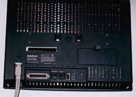
2.) Remove the screws holding
the rear cover in place. You'll need a small Phillips head screwdriver.
3.) Pry the rear cover
off. It is held by tension on the sides.
4.) Remove the screws
holding on the RF shield. There are a lot, and there is one small screw adjacent
to the power plug-in and 2 hex screws on either side of the printer port.
Once the RF shield is off you will have access to all the components on the
inside. You should see something like this below. 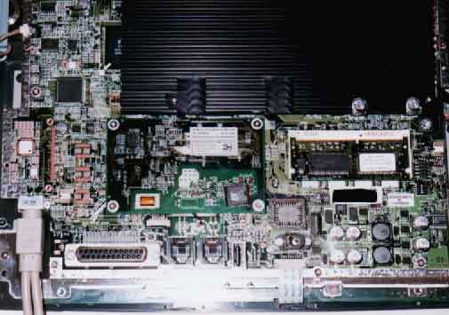
5.) To the right is my
post epoxy removal shot. If your BIOS chip has epoxy over it you will need
to remove the epoxy in order to change the BIOS chip. Use a jeweler's screwdriver
to chip at the corners and a razor to scrape the epoxy off the top of the
chip. Work slowly here. If you damage the BIOS socket you could have a hard
time getting the unit to work. DO NOT REMOVE THE EPOXY ON THE BOARD. That
epoxy will not interfere with removing the chip and removing it will certainly
damage the board. Only remove enough epoxy to allow the removal of the BIOS
chip. Here's where I got a little carried away. I used a Dremel with a cutting/grinding
wheel to remove the epoxy. I was done in about a minute - and even cut off
one of the pins of my original chip. I was very lucky I didn't damage the
BIOS socket. Use the screwdriver or dentist's pick and take your time. If
you damage the socket some people have had success wrapping a plastic zip
tie around the outside of it to hold it tightly together. My original (and
now damaged) BIOS chip is sitting on top of the modem, just left of the BIOS
socket.
6.) Remove the stock BIOS
chip and install the Badflash unit. Prior to inserting the Badflash unit gently
push the pins on it out slightly with the jewelers screwdriver from underneath.
This is soft metal so too much force could knock a pin off. Insert the new
chip into the socket but do not seat it all the way down. People have reported
a black display screen with the power LED on. Upon pulling their BIOS chip
up or bending the chip's pins out they had good contact and were able to get
a BIOS splash screen when turning the unit on.
I highly recommend the
Badflash BIOS chip. Not only are you
guaranteed the correct BIOS, but you don't have to run the risk of shorting
out an i-opener by switching the BIOS chips on a powered on unit. A big bonus
is that Jack (Badflash himself) offers a 12v chip that cannot be reflashed
when installed in the i-opener since the unit can only flash a 5v chip. Great
protection against unwanted flashing by viruses or other parties. Jack is
also now offering modified 44
pin ribbon cables also. Jack's been in business for a while and has been
helping people who have had problems with their BIOS chips. Even if you don't
need an i-opener chip I recommend you give him your business should you need
help with obtaining a BIOS for a board.
If you visit the i-appliance
BBS you can find information on BIOS flashing without removing the BIOS
chip. Keep in mind that the chip can be reflashed to the newer BIOS if it
were to somehow dial into Netpliance's server.
7.) Install your modified
ribbon cable on the IDE port on the upper left of the board. Use the middle
two rows of connectors. The i-opener features a pattern of switched pins so
the modded cable overcomes this problem. Be aware that a few boards made it
out with cut pins. Apparently these were Netpliance's early efforts at thwarting
hackers. Most people have slipped a correct length wire or resistor lead into
the ribbon cable in order to contact the pin that has been cut on the mother
board. Only a few made it out with cut pins.
8.) Install the laptop
HD as the main drive in your normal system using the 2.5" to 3.5" adapter.
Use a boot floppy and use FDISK to make the drive active and setup your partition(s).
Now, use your boot disk to get a DOS prompt and copy the Win98 setup files
onto the drive. This is the Win98 folder on the CD. This would be a good time
to copy the drivers for the video chip and modem. I'll link them later in
the article. Any software you will need should be put on the drive also, including
your ISP software.
9.) Move the drive onto
the i-opener ribbon cable and start the system. Press CTRL-ALT-ESC to enter
the BIOS with a regular PS2 keyboard. Make sure you detect the HD and go ahead
and adjust the memory timing while you're at it. The unit ships with PC100
memory so feel free to max out all the memory settings, including your cache.