|
| Features |
Info
|
- VIA KT400 Chipset
- 6 PCI slots
- Northwood Ready
- Onboardl LAN
- Onboard Audio
- 3 DDR333 Slots
- SerialATA onboard
- RAID Adapter
|
|
FIC AN19E AMD Mainboard
It has been a little
while since we last got the chance to get our hands on a FIC board, our last
test goes back in April of 2002 when we test drove their Intel P4 solution;
VC17 ended being rated quite well by us for its several features versus price
range. A bit earlier
weve also put to the test their AN11 which at the time was their latest AMD
weapon, this one as well showed us that FIC is a company capable of providing
their saying for performance and features.
After visiting FIC
at last years Comdex 2002, we have arranged to one more time get some FIC action
going on at Target PC. In this article we will be looking at their latest AMD
DDR solution, the AN19E mainboard.
The Board
Expansion on the AN19E can be considered maximal, it features six PCI slots,
one AGP 8X port (1.5v) capable of up to 2.1GB/s of bandwidth and three DIMM
slots capable of handling up to 3GB of memory from PC1600 all the way to PC2700
DDR333 memory.
One design flaw we have
found on the AN19E is the interference between the memory banks and the video
card. This little issue has been noticed on several of today motherboards
including on the previously reviewed VC17 board and generally requires removing
the video card in order to upgrade the memory.
Three fan connectors are available on the board, the first one is placed on
the lower left of the CPU socket, second is placed just below the ATX power
connector and the third and last one is located on the complete left, close
to the floppy connector.
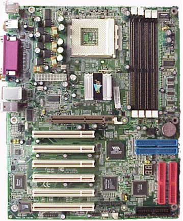
Something I didnt like on the AN19E is the placement of the IDE connectors.
I would have preferred to see the IDE connectors on the upper right side of
the mainboard along with the DIMM slots where it could provide a cleaner look
once the system is built. As for the floppy connector placing it along the
DIMM slots or simply position it in place of the
current IDE connectors would have been a perfect solution compared to its
current placement, on the very bottom of the board.

|
|